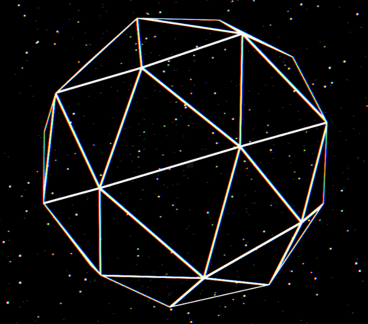
Let’s whet our appetite with a little dessert. This is my first graphics project; it won 2nd place in InnovArt 2026, showcasing few basic rendering techniques that I’m going to go through in this blog.
As a little sneak peek: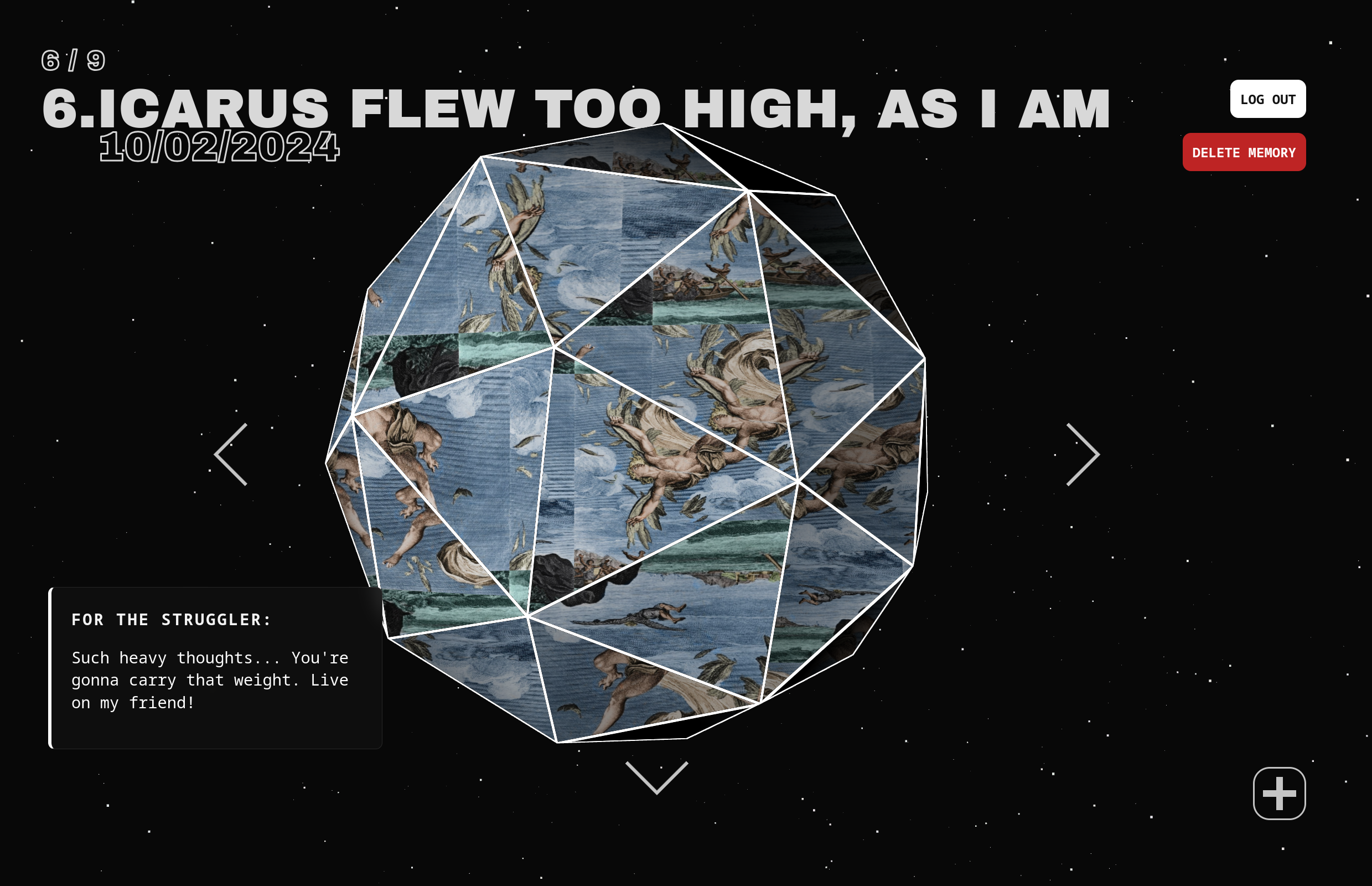
Before we continue, if you want another analysis on this project, you can check out my entry in the Binnovative Book Series 6, where I go through, not only the technical aspect (which will be covered here), but also the design and development process.
AI Usage
WEE WOO WEE WOO AI USAGE ALERT!
The project was largely done without AI, the only part that I did use AI on is CSS and a single insidious bug: Shader buffer (I made this up, not sure if it’s real or not). The problem I faced was not knowing how React DOM worked. When I was making the hovering feature, I bound the shader to 1 instance of the object. Unknowingly, when you make change to the texture, color, speed, or generally uniforms (a type of data in GLSL), React refreshes the object, causing it to lose previous uniforms context, bugging out the shader.
This was found by the Gemini 2.5 if I remember correctly. But beyond CSS and this one bug, everything else was hand written. I wanted to make this clear because I believe AI hinders learning, specifically programming learning. This entire blog is a study, this entire site is my study, how can a study be trustworthy when it was made by AI? So moving forward, every post will have an AI usage section to make it clear what I used AI for.
Setup & Background
You can check out the github repository with installation guide or enter the main web. This was done all in Three.js, specifically React-Three-Fiber, a great wrapper around the original library made for React. Why not raw Three.js? Because I didn’t feel the need to and this helped me focus more on the graphics itself.
The project went through a few revamps, going from this companion bot with a CRT for a head, to a DnD inspired dice for the companion bot (the companion bot premise was REALLY cool to me), to what we have now. I wanted to make something memorable, something to preserve life itself. So the graphics had to be somewhat celestrial, but soft and warm, like a bitter-sweet end.
Nitty Gritty
Warning: I did not think of this, most of the code was given by Yuri Artiukh, an excellent and talented graphics programmer and his recreation of Rogier De Boeve website (he has since updated his site!). But I still think it is worth breaking down the effect and what I’ve learned from it.
So let’s start off with the simplest shader: Lambertian Reflectance, a fancy name for cosine lighting. Actually, I didn’t even make this, it was built into Three.js as a part of its lighting system, but I did make the Fresnel effect!
Fresnel Effect
The wikipedia entry for Fresnel is really fancy, but it is just a reversed cosine lighting in disguise. Fresnel effect is when the light intensity gets stronger as it reaches the rim of a shape. This can be done with a cosine calculation between a face normal and the direct lighting vector:
The result is surprisingly decent: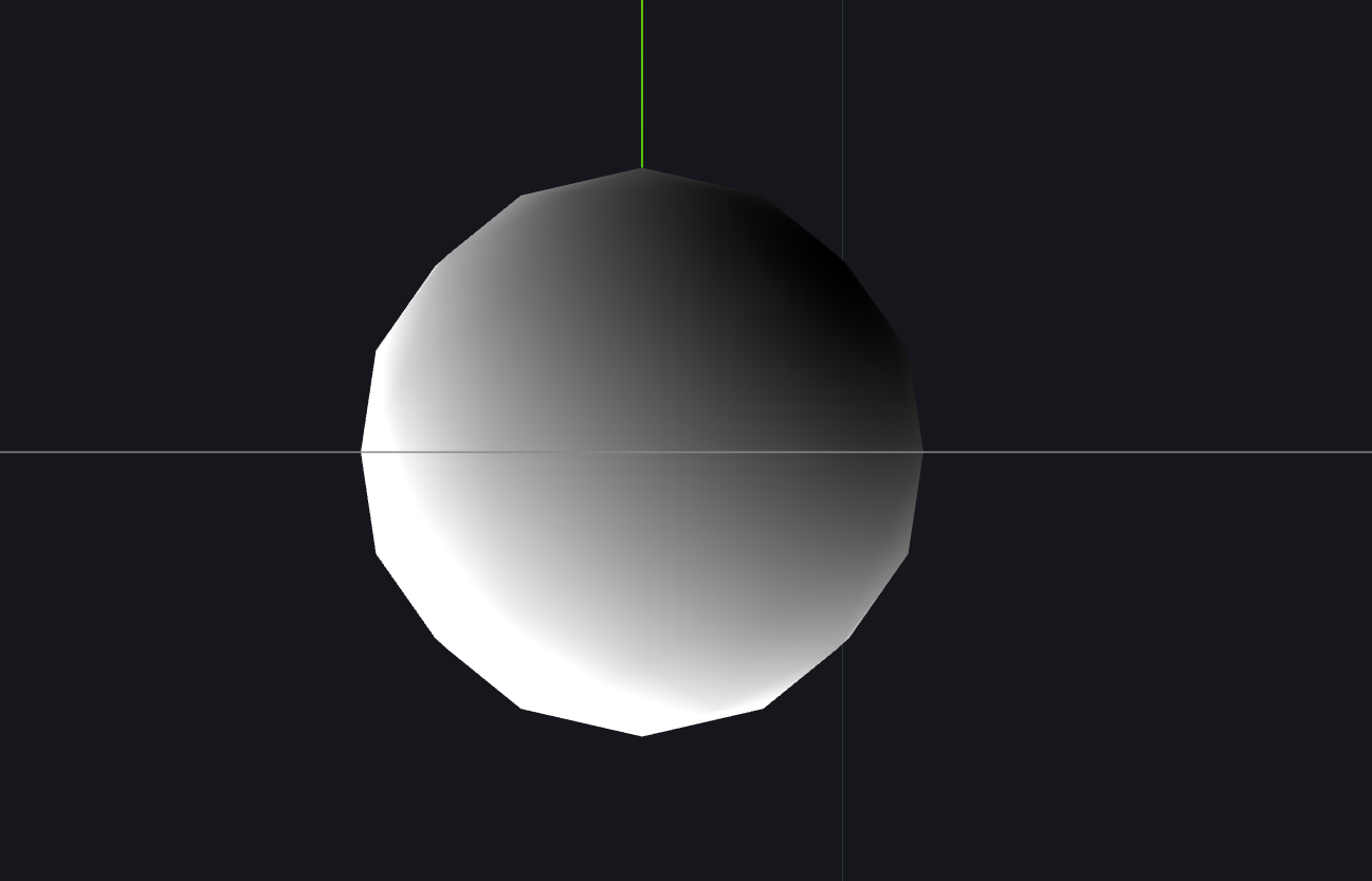
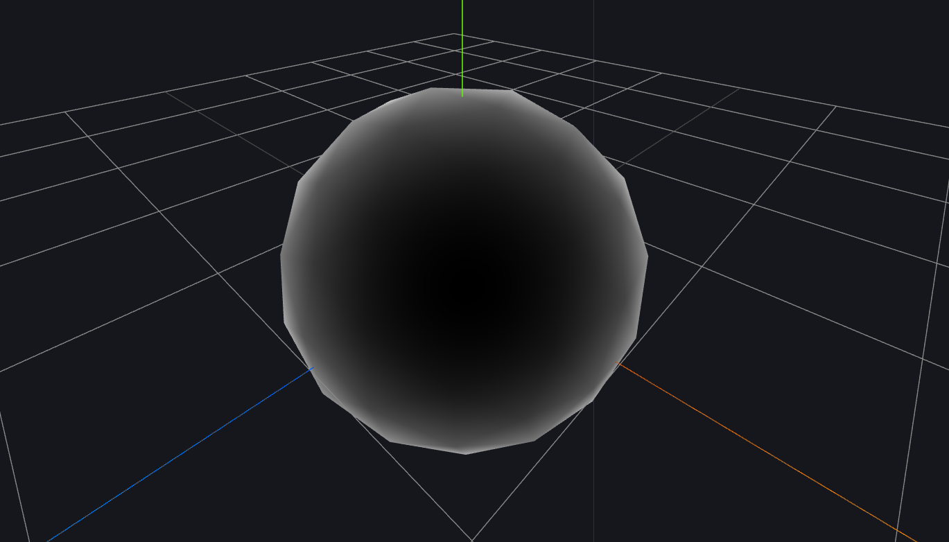
The position of light is fixed, for showcasing purposes, but as you can see, it is accurate enough. But to get the full effect and modularity, you can use this fresnel function:
This is the result: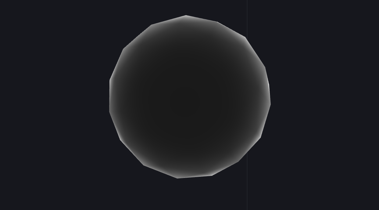
Surprisingly similar. Point is, it is pretty much an inverse of cosine lighting!
Flat Shading
BOOM. Calculus jumpscare. This is the core of Flat Shading. If you want a less math heavy explanation, check out Ned Makes Games video.
The idea is to find any 2 vector in a triangle face (because finding the 3 vertex positions from a random fragment within a triangle is impossible). Then calculate a normal from that. Finally applying that normal to the faces color data as one single color. In other words, a face have 3 vertices, we point all 3 of the vertices normals (or face normal) to the same direction, using that as our color, profit.
So the question stands, how do we get the 2 random vectors? How do we get neighboring vertices when that is impossible on a GPU? Let’s first look at partial derivative.
By the wise word of 3Blue1Brown, imagine a xy-plane:
- If you take a small step along the x axis, that’s (or )
- If you take a small step along the y axis, that’s (or )
And then we establish the fragment shader. I won’t go into the rendering pipeline, that is for another blog. For this case, all you need to know is that this process divides the image into a grid of pixels with the center of each grid being the location of a point in space. It then fills out the pixel colors based on the vertex shader data.
This image should showcase it:
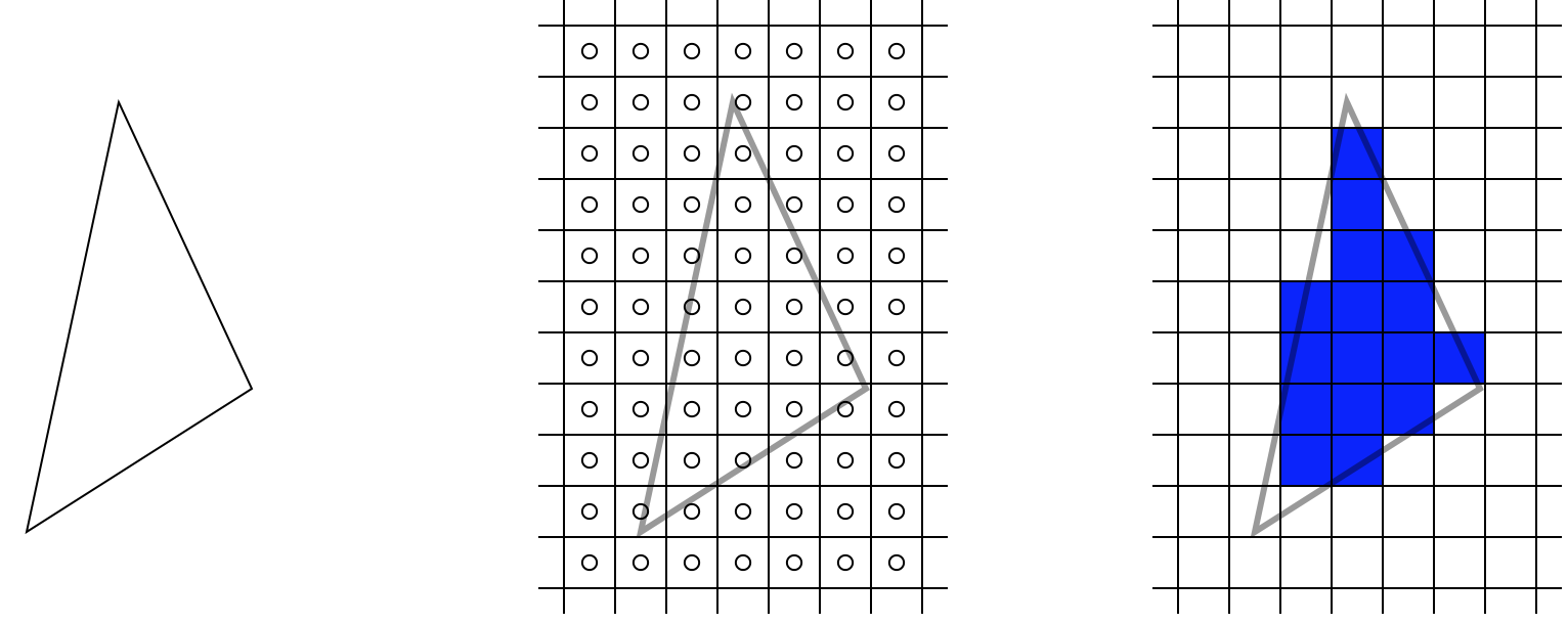
Credits to warrenm
But how does the GPU knows the coordinate of neighboring pixels? For the longest time, that has always been MY question too, since GPUs are asynchronous. Turns out, they take in 2x2 blocks of pixel instead of one pixel at a time!
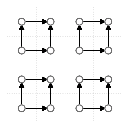
Credits to catlikecoding
Now, we combine these 2 concepts. By finding (which can be anything really, color, pixels, etc., in this case it is a 3D position) with respect to and , we are essentially getting 2 vectors, which is what we have been working to.
In code, it looks something like this (lit. what I wrote):
dFdx and dFdy do the heavy lifting here. Since we have established how GPU “sees” fragments, these functions literally “walks” along the x and y axes, returning a 3D vector (-component is something…). What is it comparing? The fragment of current instance and its neighbors |
And then we tie it all back, by getting the cross vector of the resulting vectors, normalize it, giving us the sought after face normal!
| |
We needed to do this for our refraction, creating a “blinking” effect when moved around. After getting this faceNormal, we apply it to our diffusions above, and hook it up to refraction below and we are golden!
Refraction
Here’s the neat part, refraction. Did you know GLSL has a built in function for this? It takes in a L light, N normal and eta ratio of indices of refraction.
| |
Here’s the code for the magical built-in function:
| |
The math for this is pretty well documented. As far as I can tell, this calculates the direction of light and try to emulate refraction. Here’s a more detailed explanation math-wise that I will try to explain.
The function returns a vector 3D, so as you expect, the goal of such equation is to find the direction of a vector after a piece of light is shine through a surface, we will call this
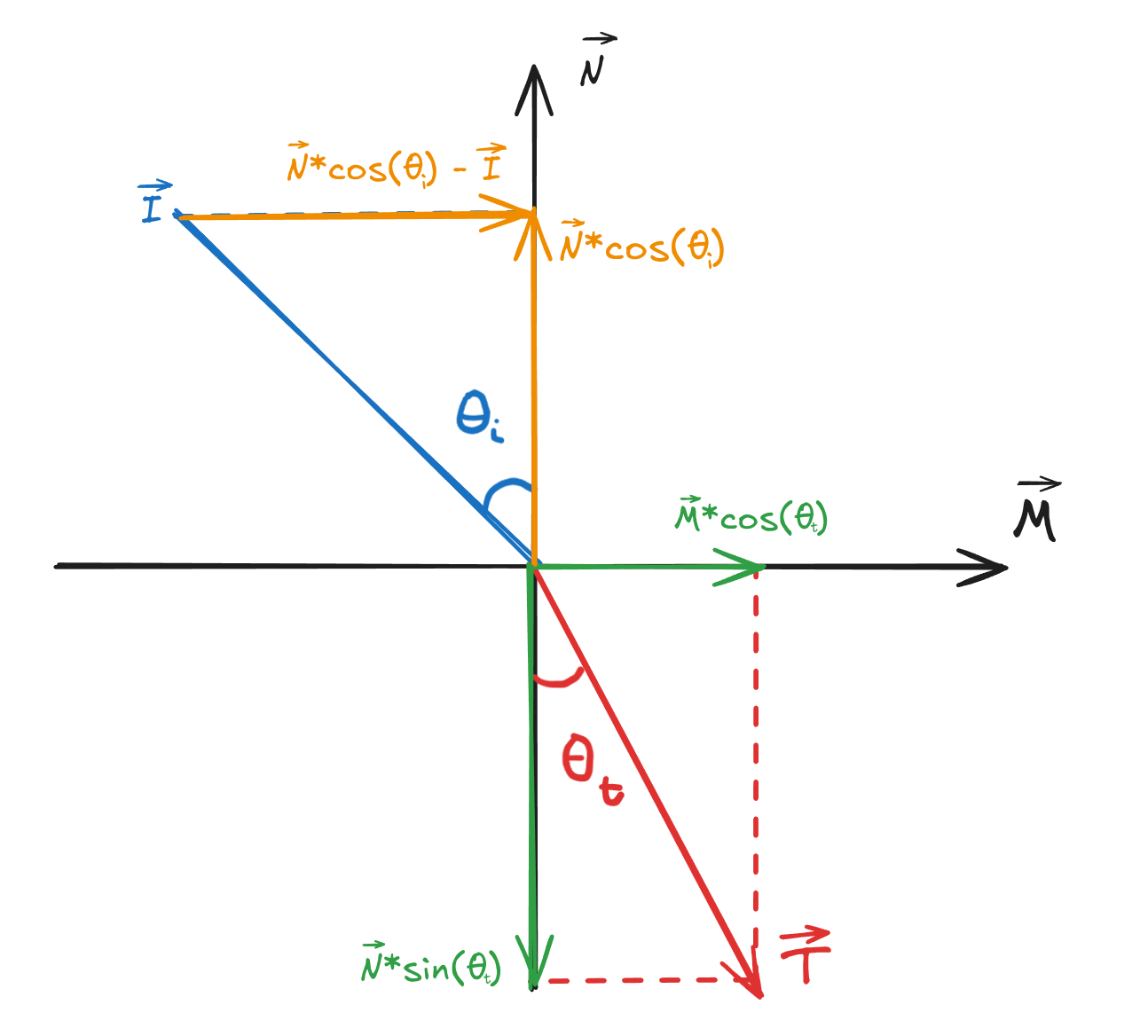
Such is calculated as:
Where is the unit vector perpendicular to (normal vector of the surface) in the plane of reflection. is given by the surface normal itself and is just the ray we casted from the camera, so now the question is how do we find .
Applying basic algebra and vector operations, is given by:
Substitute it into , we get the final equation we can use to calculate refraction:
Luckily, we can just ignore this because Khronos made it for us, but it’s good to know for debugging purposes.
To put an image behind the refraction, we just replace the object texture with the image with respect to the new UV affected by refraction:
Anti-Aliased Lines
I put full credit to Yuri Artiukh for this part’s logic. If you looked at the repo, you can also tell I took a lot of inspiration, and some part straight up copied, from this video:
Check him out, he’s an incredibly talented graphics programmer and everything I’m saying here is just a recap of what he (briefly) mentioned!
To start off, we take a look at Barycentric Coordinate: Putting point at each corner of a triangle/face. Honestly, I’m not knowledgable enough to know exactly why we do this. From what I can tell, it make the code for anti-aliased lines incredibly trivial:
All this code snippet is doing is filling out the entire face of the triangle with white and black, applying smoothstep() to create a distinct division between black and white. The black and white came from fwidth, which is just a calculation of change between 2x2 pixels, as stated above. Finally, we create a line in certain directions, discard the black parts and render it out, giving us a nicely done “anti-aliased line”
Perlin Noise
Admittedly, I was considering not talking about this, because I didn’t write most of the code, all I did was copy the cnoise() function from this repo, apply it to our gl_Position and move it around with delta time:
When rendered, this vertex shader iterate through all vertices and apply a random float value which moves it up or down in the direction of its normal, creating this “breathing” effect.
Beyond Shaders
That is about all there is to the shader, definitely more work on the fragments than vertec. This was a great little appetizer to whet my graphics programming appetite, considering I have never so much as heard of graphics programming. There were other focuses like backend development, React, JS, etc. But none of them brought me more joy than to make the shader. As this is my first blog, I feel it is fitting to whet your appetite with my appetizer. I am currently working on another graphics project that I am learning a lot from, so I hope I can entertain you with more discoveries in future blogs. Thank you for reading!